A letterbox sensor that knows when there's still post inside
An infrared beam, a tiny ATtiny chip and the guts of a cheap Zigbee door sensor tell Home Assistant whether there's still mail in the letterbox.

- Difficulty
- Advanced
- Parts cost
- Jaycar and AliExpress parts, a custom circuit board and three ASA prints
- Build time
- A big build: a board to make, three prints and a chip to program
- Skills
- Soldering, 3D printing, Flashing a microcontroller, Home Assistant
The problem
A lid switch tells you the lid was opened. That’s not the question I care about. I want to know is there still mail in the box? If the postie has been and nobody has emptied it, I want Home Assistant to know. When someone takes the post out, it should go back to empty by itself.
A lid switch can’t answer that. So this one looks for the mail itself: an infrared beam shines from the lid down to the floor of the box, and anything lying on the floor blocks it.
Fair warning before you start: this is a big build. A custom circuit board, three 3D prints and a little chip to program. My first install read “mail” all day with the box empty. The cause and the fix are below, along with every other thing that bit me, and all the files are free to download.
How it works
An infrared LED (940 nm, the kind in a TV remote) is glued to the underside of the lid, pointing down. A phototransistor (a light sensor that passes more current the more light hits it) sits under a printed false floor, looking up. Mail on the floor gets in the way of the beam.
The trick that deals with sunlight is in the measuring. The chip, an ATtiny402, reads the sensor with the LED off, then with the LED on, and subtracts one from the other. Steady light is in both readings, so it cancels out, and only the chip’s own infrared counts. When the box is empty it learns a baseline. If the difference falls below a quarter of that baseline, there’s something in the way: MAIL. It has to climb back above 40% before it says EMPTY again, so it doesn’t flicker. It checks about every 32 seconds.
To get the answer to Home Assistant I used the same trick as my chairs-up vacuum sensor: the guts of a cheap Zigbee door sensor. Inside it, a little hall-effect chip (a magnet sensor) pulls a signal line to ground when the door magnet is near. My board has a 2N7000 transistor that pulls that same line to ground when there’s mail. The door sensor thinks the door is closed, and that’s what Home Assistant sees.
What you need
Most of the parts are from Jaycar (codes below) and the rest from AliExpress. These are the parts I used:
- A custom circuit board, 104 × 46 mm, two layers, all through-hole parts so it’s easy to hand-solder. The files are in the downloads below. One footprint is wrong: see the 2N7000 note under Wiring.
- ATtiny402 microcontroller (the ATtiny402-SSN), on a SOIC-to-DIP adapter so it plugs into a DIP-8 socket. No tiny surface-mount soldering anywhere.
- MCP1700-3302E/TO 3.3 V regulator, in the TO-92 package. Mine came from AliExpress.
- BC548 transistor (Jaycar ZT2154) to switch the IR LEDs.
- 2N7000 MOSFET (Jaycar ZT2400) to fake the door sensor’s magnet.
- Two 940 nm IR LEDs, with a 150 Ω resistor each.
- Two phototransistors (Jaycar ZD1950), with 4.7 kΩ load resistors. My board started with 22 kΩ, and that’s what made it read “mail” in daylight (see Testing it).
- A 2.2 kΩ, two 100 kΩ (pull-downs on the two transistor inputs) and two 1 kΩ resistors (one is for the programming lead).
- Capacitors: two 1 µF electrolytics, either side of the regulator (mind the polarity), and two 100 nF, one beside the chip and one beside the Zigbee board’s connector.
- One LiFePO4 cell (lithium iron phosphate) with a protection board for that chemistry and a battery holder. The battery bay in my print takes a cell up to 21700 size (21 mm across).
- A cheap Zigbee door sensor. You only use its board.
- Three printed parts in ASA: the false-floor insert with the electronics bay built in, a removable cover for the bay, and a carrier that holds the LEDs on the lid. The print files are in the downloads.
- A USB-to-serial lead (mine is a CH340) to program the chip.
- A normally-closed push button for re-learning the empty box (see the fix under Testing it).
- Epoxy, silicone, a short length of flexible tube for the wires at the hinge.
- Home Assistant with a working Zigbee setup.
Print in ASA, not PLA. A steel letterbox in summer sun will soften PLA. Avoid black if you have the choice.
Wiring
The power side:
LiFePO4 cell → protection board → NC re-baseline button → MCP1700-3302 (TO-92) → ATtiny402, Zigbee board, opticsAnd the chip’s pins:
| ATtiny402 pin | Goes to |
|---|---|
| PA6 | 2.2 kΩ → BC548 base. The BC548 switches both IR LED cathodes (each LED has 150 Ω to +3.3 V) |
| PA3 | Powers both phototransistor loads, only while measuring, so sunlight can’t drain the battery in between |
| PA1 / PA2 | Phototransistor 1 / 2 collectors, each with its load resistor |
| PA7 | 1 kΩ → 2N7000 gate. The drain goes to the door sensor’s hall chip output, pulling it to ground (= “magnet present”) |
| PA0 | UPDI programming pads |
A few things that will catch you:
- The BC548 and the 2N7000 are both TO-92 and look identical. Check the markings before they go in.
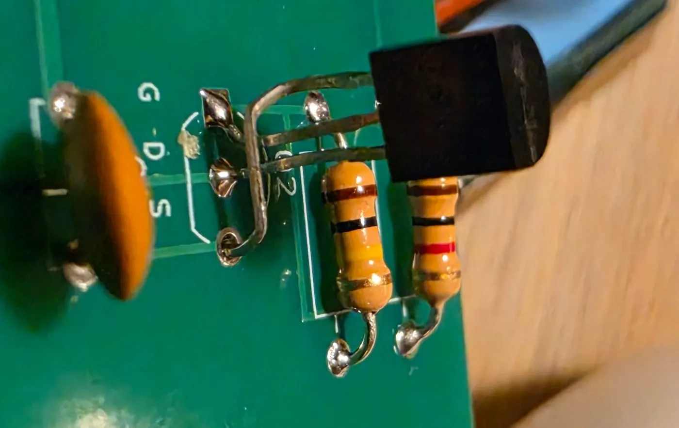
- On my board the transistor footprint has three pads in a row, so a part that’s the wrong way round just fits facing the other way in the same holes. A diode test showed me the base is the middle leg, but I couldn’t prove which outer leg was the collector. If the IR LEDs don’t light on first power-up, turn the BC548 around.
- The MCP1700 in TO-92 is pinned 1 = ground, 2 = input, 3 = output. The surface-mount version uses a different order, so don’t copy a pinout from the wrong datasheet.
- The 2N7000’s holes on my board are wrong. The silkscreen says G-D-S, but the real 2N7000 (Jaycar ZT2400) is S-G-D with the flat face towards you: the gate is the middle leg. Turning it around can’t fix that. Put the source leg straight into the S hole, then cross the other two: the gate leg into G and the drain leg into D. Sleeve one of the crossed legs so they can’t touch.
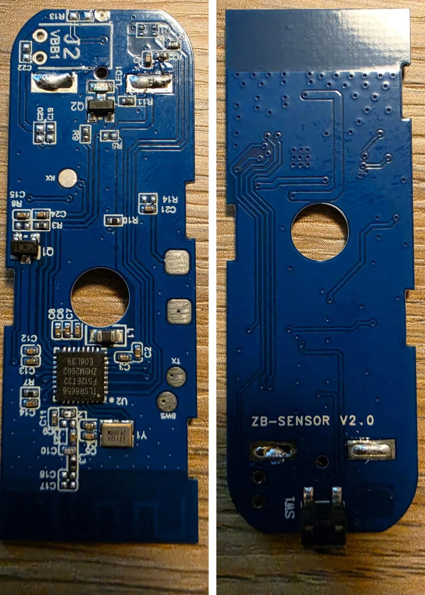
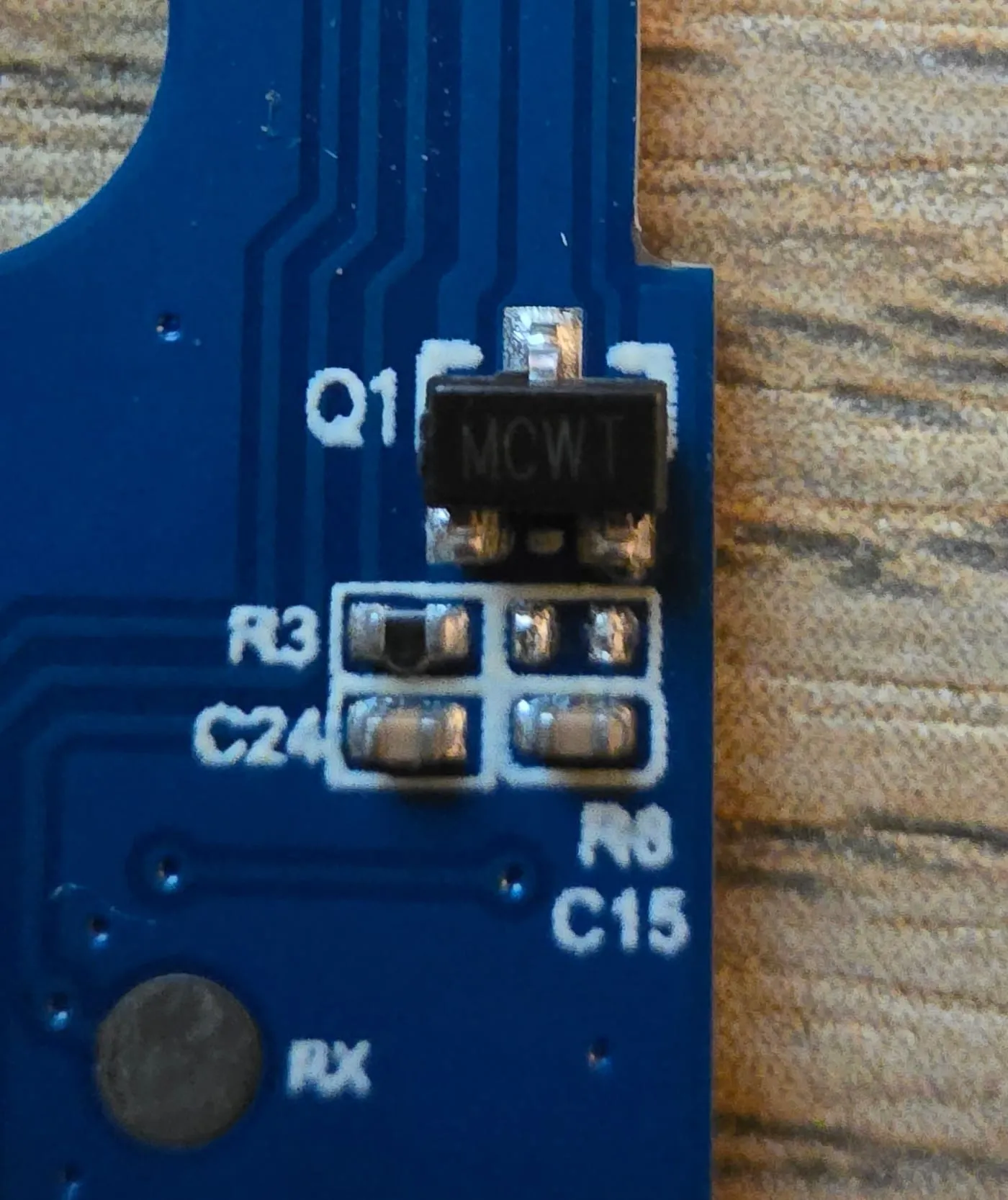
- On the door sensor board, the hall chip on mine was marked Q1. Find its output leg the same way as in the chairs-up guide: it’s the one that drops to 0 V when you hold a magnet near.
Where it all goes. The electronics sit in a bay at the front of the insert, right under the slot. The board is mounted by hand on the inside of the fixed front wall, stood off a few millimetres so any water that gets in runs down the gap behind it and out the drain holes. Components face back, towards the cover. The cell sits flat below the board. The removable cover lifts off and the battery comes straight out.
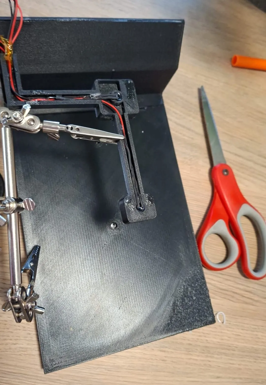
The sensor wires run along channels under the false floor into the bay. The lid LED wires run along the carrier, through a flexible tube loop at the hinge, and down a small tube up the inside of the end wall into the bay.
Firmware and config
The chip runs my own firmware, mailbox.ino, with the detection logic in detect.h and a set of tests I
run on the computer before flashing. It’s all in the downloads. Build it in the Arduino IDE with megaTinyCore
(ATtiny402), export the compiled .hex, and flash it with pymcuprog (from Microchip, pip install pymcuprog) over the lead below:
pymcuprog -t uart -u /dev/ttyUSB0 -d attiny402 write -f mailbox.ino.hex --erase --verifyThe ATtiny402 is programmed over UPDI, a one-wire programming connection. The lead is a USB-to-serial adapter with a 1 kΩ resistor, built exactly like this:
TX ─[1k]─┬─ pin 3 (UPDI)
RX ──────┘
GND ────── pin 2
TX goes through the resistor; RX joins on the board side of it. Get that wrong and nothing talks.
Running on one beam. My board has two beams, but one of the lid LEDs died. There’s a SINGLE_BEAM
setting in mailbox.ino: set it to 1 and the firmware copies beam 1’s reading into beam 2, so the detection
code doesn’t need changing. The working beam is the centre one, and on its own it catches everything I’ve
tried. If I replace the dead LED, it goes back to 0 and I reflash.
Home Assistant. The door sensor pairs like any other. It reads closed (off) when there’s mail
and open (on) when the box is empty, which is backwards to read. The plan is a template binary sensor
called “Mail in letterbox” that’s simply the opposite of the door sensor. I haven’t added it yet, and
I just read the door sensor backwards in the meantime.
Downloads
Everything I used, free to use and change. Right-click and save.
- Circuit board (Gerbers, ready to send to a board maker: zip the nine files together when you order). ⚠️ The 2N7000’s holes are wrong on this board, so cross its legs as shown under Wiring. top copper · bottom copper · top mask · bottom mask · top silkscreen · bottom silkscreen · outline · plated drill · unplated drill
- 3D prints (STL, print in ASA): false-floor insert · bay cover · lid LED carrier. They’re sized for my 153 × 255 × 85 mm box. To change the sizes, edit the Python sources (build123d): params.py (all the sizes) · insert.py · bay_cover.py · carrier.py · assembly.py
- Firmware (Arduino with megaTinyCore): mailbox.ino · detect.h · test_detect.cpp (the tests, run on a computer)
Step by step
- Measure your letterbox, and write down which way the slot faces. Mine is 153 mm across the slot, 255 mm deep and 85 mm tall.
- Print a small-scale test of the parts first. My 30% test print confirmed the shapes before I spent the ASA on the full size.
- Check your sensor height against the false floor as soon as you have the parts. With my flat floor, a phototransistor much taller than about 10 mm won’t fit at all.
- Build the board, but leave the chip out. Feed it about 3.6 V (a full LiFePO4 cell) and confirm about 3.3 V at the socket’s pin 1 before you fit the chip. My regulators came from AliExpress, so I checked a few from the bag.
- Fit the chip, make the UPDI lead and flash the firmware.
- Bench test it (below) before anything goes near the box.
- Wire the 2N7000 to the door sensor board’s hall chip output and ground, and pair it.
- Fit the LEDs into the carrier and epoxy it to the lid. Fit the sensors in the floor and route the wires.
- Let it learn its baseline in the box, with the box empty and the lid shut, before you glue anything. It takes the first 8 good readings, about 4 minutes.
- Leave it for two or three days and compare Home Assistant’s history against sunrise and sunset.
Testing it
On the bench, with the kitchen light on, my one working beam read about 960 with the LED off and 32 with it on, a difference of about 930. That became the baseline: EMPTY. One envelope dropped the difference to 103, about 11% of the baseline (the cut-off is 25%), and it read MAIL within about 2 seconds. Take the envelope out and it went back to EMPTY.
Then end to end, with the normal firmware and the Zigbee board connected: Home Assistant showed MAIL about 30 seconds after a letter went in, and EMPTY when it came out.
Where it’s up to. Installed in the box, Home Assistant showed MAIL from about 8:30 in the morning until 6 pm, with the box empty. It went EMPTY around sunset, then flapped between MAIL and EMPTY for a while after dark. We brought it back inside onto the test stand and it worked fine.
My reading of it: the baseline is learned from the LED difference, so steady light should cancel out. But only if the sensor isn’t swamped. With a 22 kΩ load resistor, the LED alone pulls the sensor almost to the bottom of its range (960 down to 32). In daylight, the LED-off reading is already pulled down, so the LED has little room left to make a difference. The difference shrinks below 25% of a baseline learned in the dark, and it reads MAIL. At night it recovers.
The fix, in this order:
- Change the load resistor from 22 kΩ to 4.7 kΩ (2.2 kΩ if it’s still swamped). A lower value makes the sensor less sensitive, which gives it headroom.
- Add a re-baseline button. The chip has no spare pin, so the button cuts the power instead: a normally-closed push button in the battery positive lead, under the false floor. Hold it about 3 seconds and let go, with the box empty and the lid shut. The first 8 good readings become the new baseline.
- Keep the programming header reachable, or bring a three-wire lead out, so any later change is just a reflash.
- Leave it two or three days and check the history again. Only if it still drifts by day: firmware changes, like treating a half-swamped sensor as “not sure, hold the last answer”, or re-baselining at night.
Lessons learnt
I glued it before it ever learned its baseline in the box. The baseline was learned on the bench, and the real box, in daylight, is a different place. It read MAIL all day. Let it baseline where it lives, with the box empty, before anything is glued, and give it a way to re-baseline later.
A bigger load resistor isn’t “more sensitive” in a useful way. With 22 kΩ the sensor was swamped: the LED alone pulled it nearly to the floor, so daylight left no room to see a change. My own notes once said to raise the value. That was backwards. Lower the resistor and the sensor has headroom. The values I started with were only ever starting points: the real beam in my box is about 62 mm long, not the 100 mm I’d designed for, so there was more signal than planned. Set the resistors from real readings: dark, room light, direct sun, LED on and off. With through-hole parts it’s a two-minute swap.
“All checks passed” lied, three times. My computer checks on the 3D model said everything fitted while the files had a sensor hole cut from the wrong starting point (the light path was left solid plastic), a drip wall printing as a floating bar, a wire bridge with no base, a wire run not joined to its housing, and a skewed access opening with a notch cut through the front wall. Cross-sections through the model found every one. The 3D picture didn’t. Slice it and look.
A ground pad sitting in a ground pour isn’t always connected. My own continuity check assumed it was. KiCad’s checker found the chip’s bypass capacitor ground floating, because the little copper spokes that join it to the pour never formed. It would have worked on the bench and played up in the box. Every ground pad now gets a real copper track, and I trust KiCad’s own design rule check, not my own script.
One beam is enough. With the second LED dead, I ran on the centre beam alone, and it still catches everything. The firmware setting means swapping back to two beams is a reflash, not a rewrite.
A steel letterbox is a cage for radio. In an earlier test the metal box killed the Zigbee link. That’s why the electronics sit right under the slot: it’s the only opening in the steel that’s always there. A Zigbee router (a device that relays the signal) a few metres away is part of the plan, but not set up yet.
Don’t fuse the programming pin to anything else to get a button. The chip has no spare pin, and the only one you could free up is the programming pin. Turn that into a reset pin and you can’t program it again. So the re-baseline button cuts the power instead.